When to consider this approach
- Mixing vessels where the agitator geometry and speed range are available
- Processes that need continuous trend or a separately defined point alarm
- Applications where an acceptable response time can be stated
DIRECT ANSWER
A stable result begins with the tank drawing and operating cycle. Mount the sensing path away from blades, shafts, baffles and the filling stream where possible, then choose a technology and damping strategy that still responds fast enough for the control or protection duty.
APPLICATION BOUNDARIES
SELECTION FACTORS
Use this list to prepare a traceable quotation request.
TECHNOLOGY COMPARISON
| Starting point | Potential advantage | Application boundary |
|---|---|---|
| Non-contact radar | No probe exposed to blade loads | Beam path, false echoes, foam and moving surface require review |
| Guided wave radar | Guided signal can reduce dependence on a free-space beam | Probe must avoid mechanical contact, coating and lateral loads |
| Hydrostatic or DP | Not based on the moving top-surface echo | Density, vapor pressure and impulse or seal arrangement affect result |
| Capacitance | Simple continuous or point arrangement for suitable media | Coating and dielectric variation can dominate calibration |
EXAMPLE APPLICATION
Mark the mixer shaft, maximum blade envelope, baffles, inlet and proposed nozzle on one drawing. Review readings at stopped, low-speed and maximum-speed conditions before finalizing signal damping.
RELEVANT INSTRUMENTS
These products are available for selection and inquiry. Unverified model-specific Technical Facts remain isolated until the controlled technical review is complete.
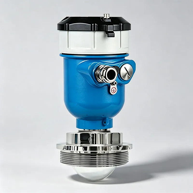
TYCK OCEAN series · Configurable industrial instrument
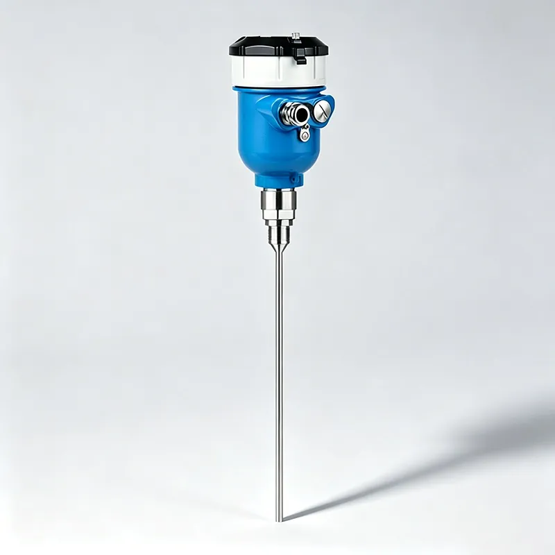
TYCK OCEAN series · Configurable industrial instrument
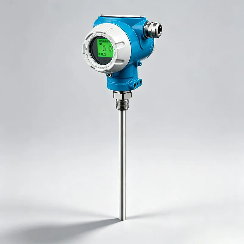
TYCK OCEAN series · Configurable industrial instrument
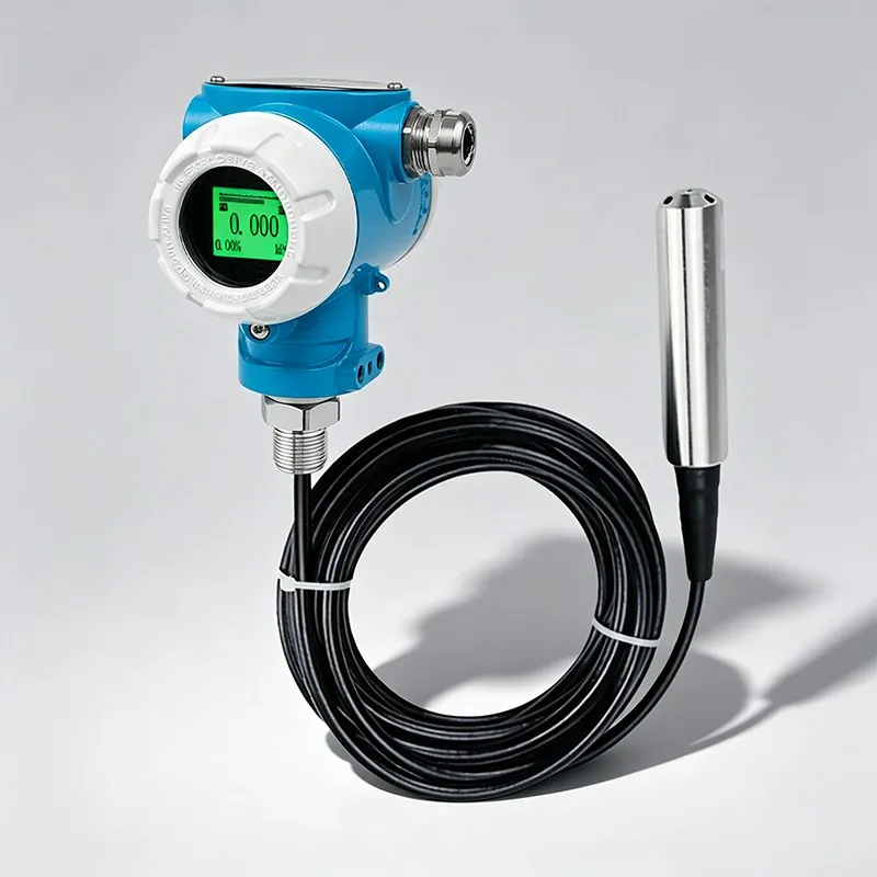
TYCK OCEAN series · Configurable industrial instrument
FAQ
Last reviewed:
Damping can reduce valid short-term movement, but it cannot correct a blocked signal path, blade echo, coating or unsuitable technology.
The exact location is vessel and model specific. It should normally keep the radar beam clear of the agitator, inlet stream and strong internal reflectors, using the controlled installation instructions.
ENGINEERING SUPPORT
Share the medium, operating envelope, installation and required output. We will flag missing information before confirming a model.
WeChat ID +86 18019926927